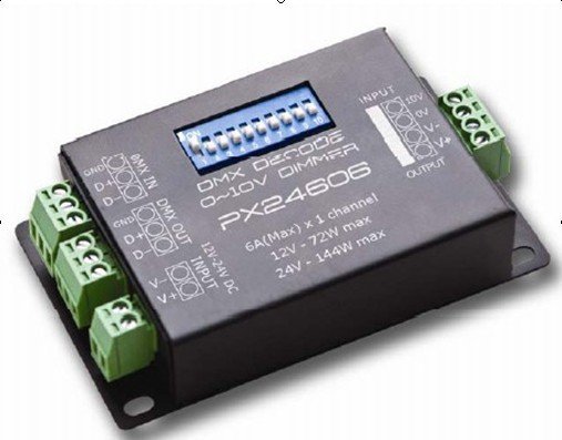
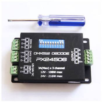
DMX RGB Decoder 3 channel control DC12V/24V 3A/CH
The 3-channel DMX controller controls 3 DMX channels. It is actually a real dimmer block for rgb tapes. It is one of the cheapest decoders on the market. Production China.

Description
The DMX24506 uses a modern microcomputer Control technology and converts the widely used Digital signal DMX24506 in the analog. As options, you can But use from 1 to 3 channels with 256 shades of gray. Also The device can be used as a PC connector Controlled digital lighting controller and analog Modulator of illumination. As a rule, the decoder is used for LED building lighting control.
Functions
- Compliance with DMX512.
- 256 levels of brightness, full color control.
- 3 channels with a current load of up to 3A on each channel.
- Excellent effects thanks to the control system.
- Thanks to the mechanism for selecting colors, you can control from 1 to 3 colors.
- Independent DMX address setting.
- Ability to specify the requirements of the customer.

| Specifications | |||
| Control Channels | 3 channels 1) | ||
|---|---|---|---|
| Values | 256 channel values | ||
| Output power | 3 Amperes per channel 2) | ||
| Effects | Inclusion, intensity, mixing | ||
| DMX | Set the address of the DIP switches. | ||
| Working voltage | 12-24V | ||
| Operating temperature range: | 0 ~ 50 ° C. | ||
| Overall dimensions: | 86 (mm) * 51 (mm) * 17.8 (mm). | ||
| Power consumption in standby mode: | <1W. | ||
| Weight: | 110g. | ||
| Optional | Power can be increased by amplifiers |
Interface Description
Input DMX IN and output DMX OUT interfaces can be interchangeable. Address setting interface For usage procedures, refer to the «DMX address code table». The table of addresses of codes of series DMX. 12-24VDC input, power supply for decoder and lamps.
Driver Output Interface
The common anode, V + and R, G, B interface can control the RGB module or single-color module. WHO- The ability to control the output current in relation to the actual load. Notes: Connect the positive lead and RGB wire of the common anode of the RGB module. To the output interface of the decoder. Connect the positive terminal of the monochrome module to the V+ on the decoder, and the negative output to the One of the RGB module outputs according to the color of the LED. Connect several single-color models to one decoder, with their positive output Connect to the V+ terminal on the decoder.
Connecting the DMX-512 signal
The DMX512 signal uses a CAT-5 cable or a three-wire braided cable, while the DMX- The signal has a positive (+) and negative (-) poles. When soldering the DMX- Should be observed so that there is no short circuit between the positive (+) And negative (-) poles, and then connect the cable Corresponding to the input interface of the DMX24506.
Обсуждение